Sunday, 20 October 2013

Part 11 - LC (Low Cut) Filters or Sanders Filter

In the name of Allah, the Most Beneficent, the Most Merciful.
Assalamualaikum w.b.t

In this video, Jose will shows us about LC Filters also known as Sanders Filters. Jose has build up LC filter by himself which is made from ferrite core with shrink wrap tubing (on top) and a capacitor (at the bottom). The green wire is the magnet wire which is also wrapped by shrink tube that surround by the fair right core. 

Another filter is the new version of filter

Here's a little pictorial on LC filtering. Use a piece of servo wire and strip off the signal wire so left with BLACK-RED. For constructing the inductor (the L in LC filtering), loop both wires through a ferrite ring as many times as it'll fit, but at least >5 times. Use both wires as that gives a little better attenuation of the ESC noise as the inductor now becomes a common mode inductor.

Then simply solder a 470...1000uF/25V electrolytic capacitor (the C in LC filtering) to the side that attaches to the audio/video transmitter and the camera. The capacitor is polarized, hence it has a + and - pole. The - pole is marked with a stripe and - symbols on one end, can't miss it, that needs to go on the BLACK wire, the + pole is on the RED wire. This will clear up any ESC noise that normally causes lines in the video. The parts we'll need are:
  • Length of servowire
  • Ferrite ring
  • 470...1000uF 25 volt electrolytic capacitor


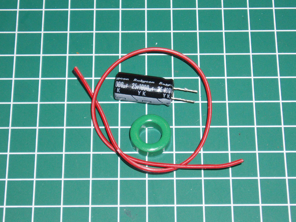
Fig 1. Here's the parts you'll need, available from Radio Shack and similar stores.


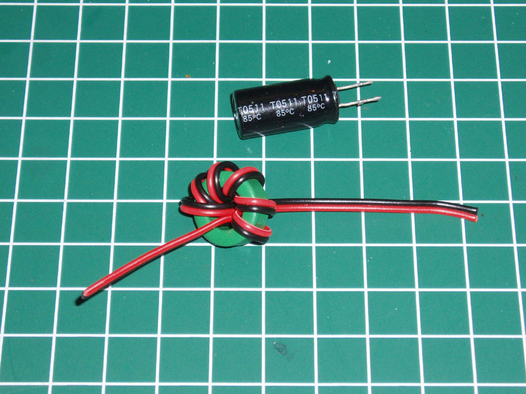
Fig 2. Here's the servo wire being looped through the ferrite ring.

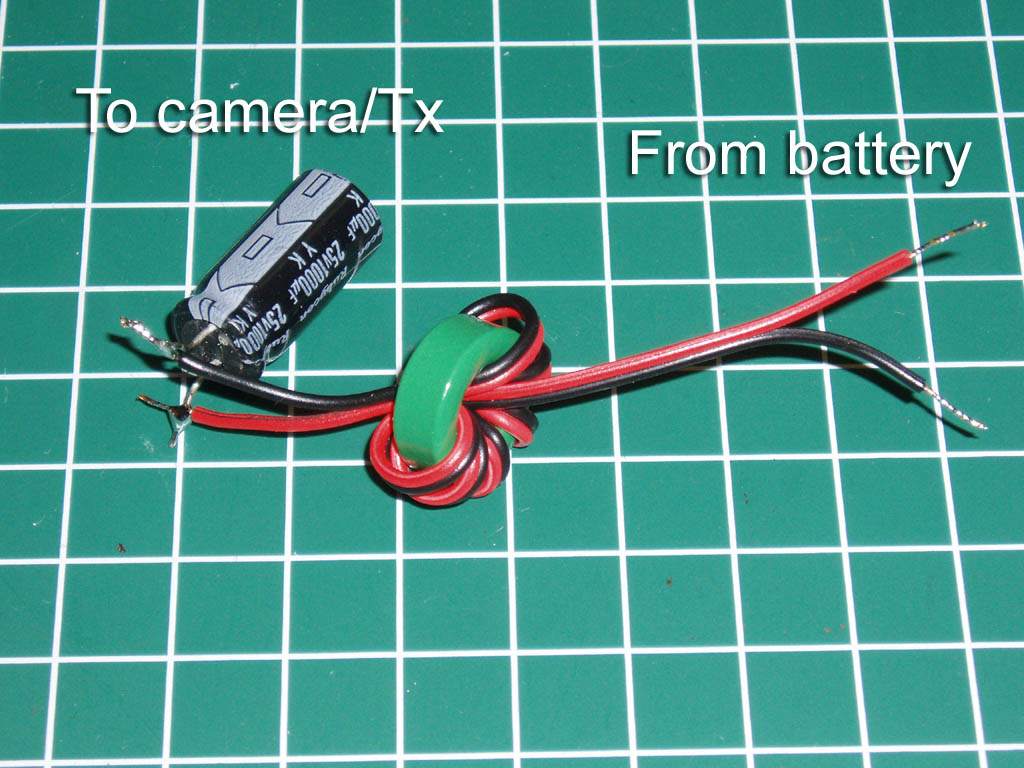
Fig 3. And that's the finished LC filter with the capacitor soldered on.


All that is required now is some shrink wrap to keep the inductor tightly wound and to go over the exposed electrical contacts. That's it, simple yet effective and all that from a mere few money worth of electronic parts.

Next is Jose showed the wiring diagram ,


Wiring diagram of filter to the battery LIPO which is divided into an old design and new design.

Old Design 

From the diagram, the ferrite core has been drawn with green lines because it is showed that the ferrite core has been wrapped around by magnet wire with 20 turns around the core and solder it on with another positively (red wire) of LIPO battery (+). Another negatively (black wire) get branches off  from LIPO IN battery to the LIPO OUT (-). The other side negatively (black wire) goes to negatively of capacitor (470mF, 35V, CAP) and the positively of capacitor connected to the positively of the ferrite core which is goes to LIPO OUT (+).   If we want redraw it back, the same capacitor will be vertical instead of horizontal at the drawing before. It is in parallel connection which is positively goes to LIPO (+) and vice versa and only positively goes through the ferrite core. 


New Design

According to the old design, the capacitor has both positive and negative leg are at the both side. Go to the new design, Jose used a different capacitor which is the positive and negative leg on   the same side. 


In this design, Jose has bought ferrite ring which is 0.68 inches in diameter instead of using a ferrite core. Instead of wrapping the magnetic wire on the ferrite core, the ferrite ring can be wrapped by the 24G wires and the way on how to do it is as above (scroll up). The black wire is pass through inside the ferrite ring (to make it more compact). The capacitor is a bit smaller than previous design which is 470mF 25V and the positive leg goes to LIPO(+) and the negative leg goes to LIPO (-). In the design, we can see the LIPO IN and LIPO OUT where the voltage of LIPO OUT goes to devices. If we have FPV camera, the LIPO OUT will connect to the FPV camera. The complete LC filter will be wrapped with heat shrink tubing for more neat.


An example if FPV camera and transmitter will be connected with the LC filter


Till then~


Monday, 7 October 2013

Part 10 ~ u-Blox CN6-02 GPS

In the name of Allah, the Most Beneficent, the Most Merciful.
Assalamualaikum w.b.t

In this video, Jose showed the u-Blox CN6-02 GPS Receiver version 2.0 tutorial and introduced the features basically. Jose showed on how to test the GPS without using CIRUS board.


Start-up


Open the Arduino files > Look for the #define GPS_PROTOCOL GPS_PROTOCOL_UBLOX > Looking by the comment (the grey colour one) which is GPS_PROTOCOL_UBLOX without GPS > change the other comment to GPS_PROTOCOL_UBLOX (just cut and paste) and it says {<<<Select this for Ublox LEA-6 (CRIUS board and others)}


Under the comment, there are some data says #define SERIAL2-BAUD (the black colour one) and the comment says 38400 // GPS Port (don't ever change it). Thus, because this board come with Baud rate which is as default parameter : 9600 that we need to programmed for connected to CRIUS board and set the Baud rate as 38400 and don't have to. The reason why we don't have to is because it's build into sketch file  and there's coding here that automatic to set the 38400 that is refresh the rated to 10M hertz. So, no matter what we set the GPS using the u-Blox when it's powered by the CRIUS board, the CRIUS board should gonna reset all over again to 38400. So, don't bother making any Baud rate changes on our GPS and how Jose will show how to play with it. 


Installation Ublox Ucenter software:

Go to google > Type ublox ucenter > see  the first link come up which is " ucenter GPS evaluation software - uBlox" > click on that link > and the ublox website will come up > and can download the manual and specification of the GPS > see the link "ucenter download version 7.02 (internet connection is required for installation) > open/save the link.


While the GPS unit has been attached to USB unit and it's got the green light ON > come up with ucenter software (that has been installed) > first thing we have to is connect to the GPS, there's a little an arrow at upper corner which is showed CONNECT and click on that > select COM4 (if using Window 7, click on START button, click on Device and Printers and we can see USB_SERIAL CH340 COM4 and it by default and it will automatically connect at the Baud rate.

*There's a little icon there which is looks like a magic wand. It is  an auto Baud rate. It will try to communicate with the GPS receiver automatically and at lower right we can see COM4 9600, and that's it will communicate to GPS 9600 that we have set before. 

We may see on FIX MODE at the right upper corner which is No Fix if we are indoor, so we are no picking at the GPS position and vice versa. 

So easy way to talking to the GPS is click on VIEW button and select BINARY CONSOLE and we can see data come across which is the scroll bar is moving that shows it is continuously collecting data that means we are talking to GPS receiver and the GPS is working.

Another way to test is connecting the laptop to the GPS which is take it outside. Start the communication, set the Baud rate as 9600 and a couple of seconds we should see the GPS position and the numbers of satellite > Click on VIEW button and click on Google Earth (while we have the WIFI connection to download the plugin to start up the Google Earth) > If GPS has the nice satellite position, we can actually go down to GPS coordination that the GPS is picking up. 

Tips: We can do at the outdoor venue so that we can see through the Google Earth to find the connection. Try to walking with the laptop in the outdoor so that Google Earth will change the features because the GPS is moving around (while walking). So, then if we are outside, picking up only 1 satellite (click on an "empty box" at the upper right corner). And this is how we test the GPS WITHOUT the CRIUS board. 


Start up the Ublox software > click on the little icon upper left corner > select COM4 and it will automatically connected to Baud rate 9600 


If it's not working:
Click on the little icon looks like sine wave upper left corner > select 9600 > click on VIEW button > select Binary Console and we can see the data come across and we got the connection to the GPS receiver and it's working.


If we want to play around with it:

Go to VIEW button > select Google Earth and we can play with the map and etc.

Tips: Otherwise, if doing nothing, DON'T ever try to configure it using Ublox ucenter which is set the Baud rate on it because when the CRIUS board power up the GPS, it is gonna pull that info to the sketch file and it will automatically set to 38400. So, don't ever bother to set the Baud rate of ucenter because it is a waste of time. 


Here's are the specification of the u-Blox CN-06 GPS Receiver ver. 2.0 and the tutorial's video.

Features:
 •Standalone GPS receiver
 •u-blox NEO-6M GPS module
 •EEPROM for save configuration permanently
 •Build in 25X25mm active antenna
 •UART (TTL) port with EMI protection
•Rechargeable battery for backup/hotstart
Default parameter
 •Baud rate : 9600    

If this GPS receiver used for I2C-GPS NAV Board, it must be changed to baud rate 115200 / update rate 5hz.

Other
 •Dimension: 28mmX33mm
 •Height: 12.5mm
 •Weight:16.5g/18.9g(include cable)
 •Hole diameter: 3.1mm
Package content
 •CN-06 GPS receiver x 1
 •UART 4Pin cable 300mm x1


Till then~


Monday, 30 September 2013

Part 9 ~ MinimOSD and SSOSD

In the name of Allah, the Most Beneficent, the Most Merciful.
Assalamualaikum w.b.t

This part, Jose has showed the data on the screen and also the connection based on the diagram.

From the video transmitter, super simple OSD are appeared on the screen and the rest of data is from MinimOSD. The left on the top corners 11.34Volt is for the mian LIPO battery and go through to AC Filter and branches off into a UBEC which is 5V into the CRIUS board and the 12V going through to the Super Simple OSD for battery number 1 (refer to the diagram given). 

The middle on the top of screen is a counting number of minutes and seconds that Super Simple OSD had received power. So, when it is turned ON, it received 12V and right through the main battery connection and it's start counting up.  It can used as indicator for time in flight roughly. Next, the right on the top of the screen which 11.71V is a lightbulb battery voltage for video transmitter.  And there's power of FPV including the camera and the transmitter. Everything else come over from telemetry of MinimOSD. The arrow under the number of counting (minutes and second) is directly to the HOME. Based on the video, the data under 11.34V is an altitude at HOME when powered at the CRIUS board(took off 100 foot elevation) and the other data under 11.71V is correct altitude when take off (took off 200foot elevation). For data which is showed as Wp o 214955F XE OF is a waypoint data to the next distance waypoint and the arrow showed to the next distance waypoint. For the line shown is a compass reading and under it a warning messenger can come up for example BATTERY LOW. Under the messenger, there's longitude and latitude and there's an icon of satellite and showed the number of satellite beside it. Thus, beside the number of satellite, there's GPS fixed that has been locked. Beside the GPS fixed is a throttle percentage and under the percentage is the mode of CRIUS board which is STABILIZE. That is for combination of MinimOSD and Super Simple OSD on the screen. 

Next, Jose has showed the diagram of Super Simple OSD and MinimOSD has been wired up. 

From the main LIPO battery, it go through to the AC Filter to cleanse out the noise and it gets branch off and one in goes to 5V UBEC and comes down to powered the CRIUS board and the CRIUS board powered the MinimOSD board. The other branch (12V) before it gets to UBEC (whatever the battery voltage is) goes to the top of connector of Super Simple OSD (SSOSD). And the other side is a FPV battery voltage and there is FPV battery voltage (lower corner of the diagram) goes to AC Filter and it is branches off into the SSOSDand the other branch goes into the FPV camera that gets 12V to power up. There's battery main input and FPV battery input into SSOSD. 

The MinimOSD is acting the main of the video OSD. It is tagging the telemetry data of TX and RX and it's combining with the video signal from FPV camera. The ground (GND) connected to grund (GND) of the camera and the very important is we have to connect the video in signal and video out signal on the same rail in MinimOSD board. Beside the GND in and video in are GND out and video out which is get send out to the input of SSOSD which is into the GND in and video in. Basically, the MinimOSD is tagging the telemetry data and live camera sending that to the input of the SSOSD then SSOSD will outputing the combination of video and telemetry data for MinimOSD and the battery input has sending it out through GND and video out into the video transmitter which is getting power by same battery as the camera  and as the FPV. So, that is MinimOSD and SSOSD getting stated and can reverse it which is can make the SSOSD to the primary one and have a feed the video in to the camera and have the video out into MinimOSD and the MinimOSD go out to the video transmitter. Can choose either way but the other way (not reverse one) is the better way. 

Here, I'll attached together with the video for the clear vision and picture.


Till then~


Saturday, 21 September 2013

New in Blogging World

In the name of Allah, the Most Beneficent, the Most Merciful.
Assalamualaikum w.b.t

Alhamdulillah, finally I'm having my own blog for this year. Well, I'm 24 years old and currently studying at Universiti Malaysia Pahang in Mechatronic Engineering programme. In this blog, I would like to share some information about journey of making UAV (Unmanned Air Vehicle) whereby I'm doing for my final year project. I just hope this blog gives more benefits to anybody which love in aeronautical knowledge. Well, just wait for my next post.

Till then..